
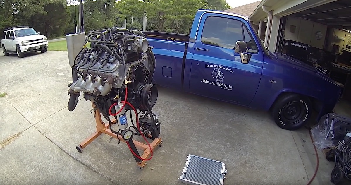
 Electrical wiring in a vehicle can sometimes get pretty tough. Cars nowadays come from the factory with a multitude of sensors, and those sensors work together with the car’s computer, which is referred to as the engine control unit (ECU). If you’re in the process of performing an LS swap, but find yourself stuck playing with electrical gremlins, have no fear. Take a look at the video above from YouTube user AGearhead4Life (aka Mark Burch). He explains to us how to properly wire a GM factory ECU the easiest and most cost efficient way.
Sensors You’ll Want To Consider
Before beginning the wiring process, Burch recommends that you have your factory ECU flashed to disable the vehicle anti-theft system (VATS) sensor. He also recommends that now would be a great time to have the rear oxygen sensors (O2) sensors disabled as well. Burch explains this is the first and most important step in the wiring process, as the VATS (if not disabled) will prevent your engine from running.
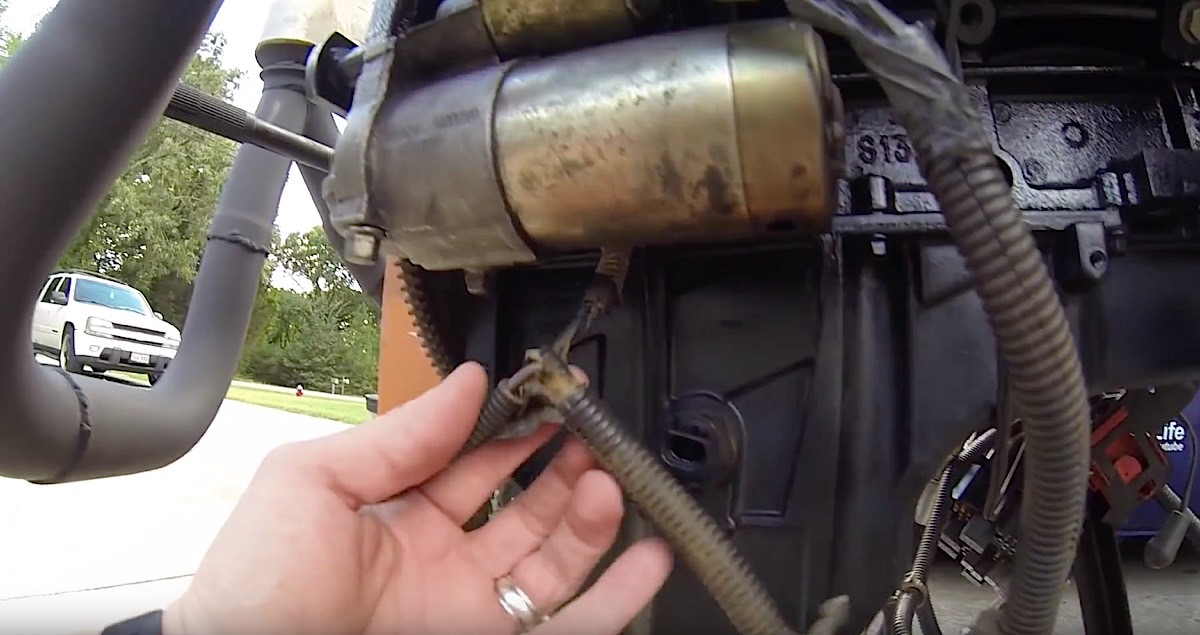
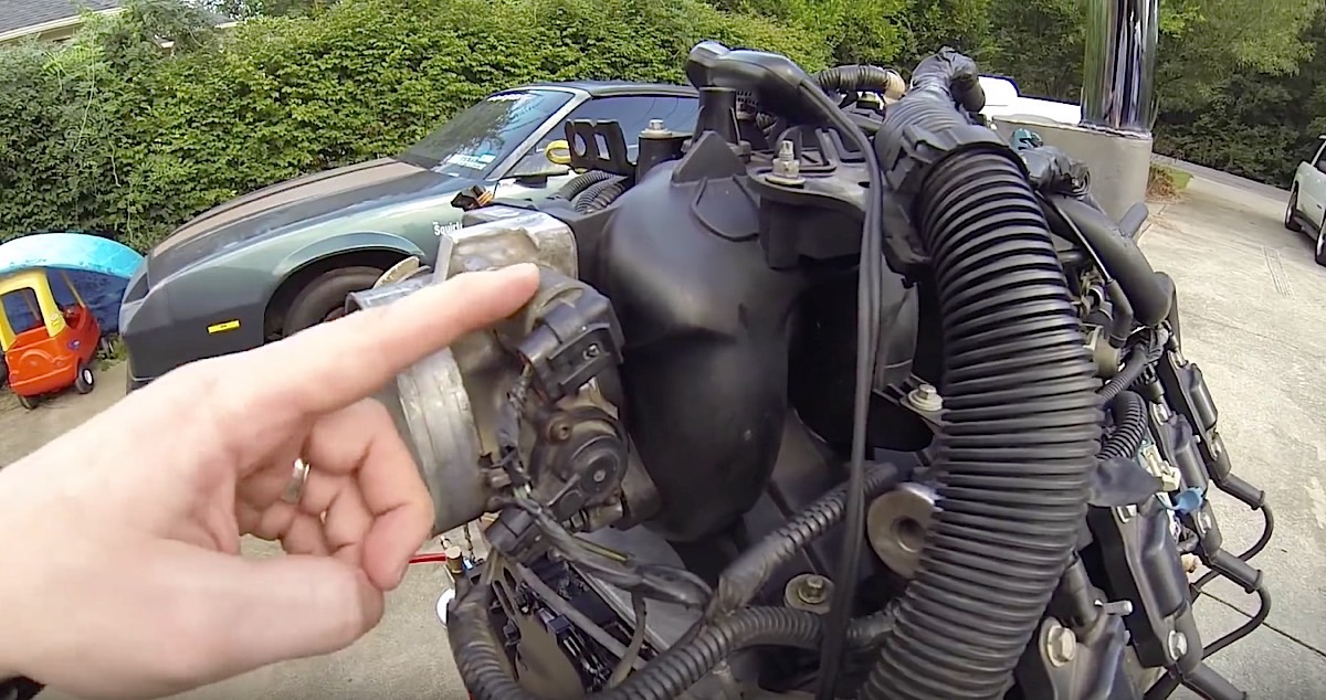
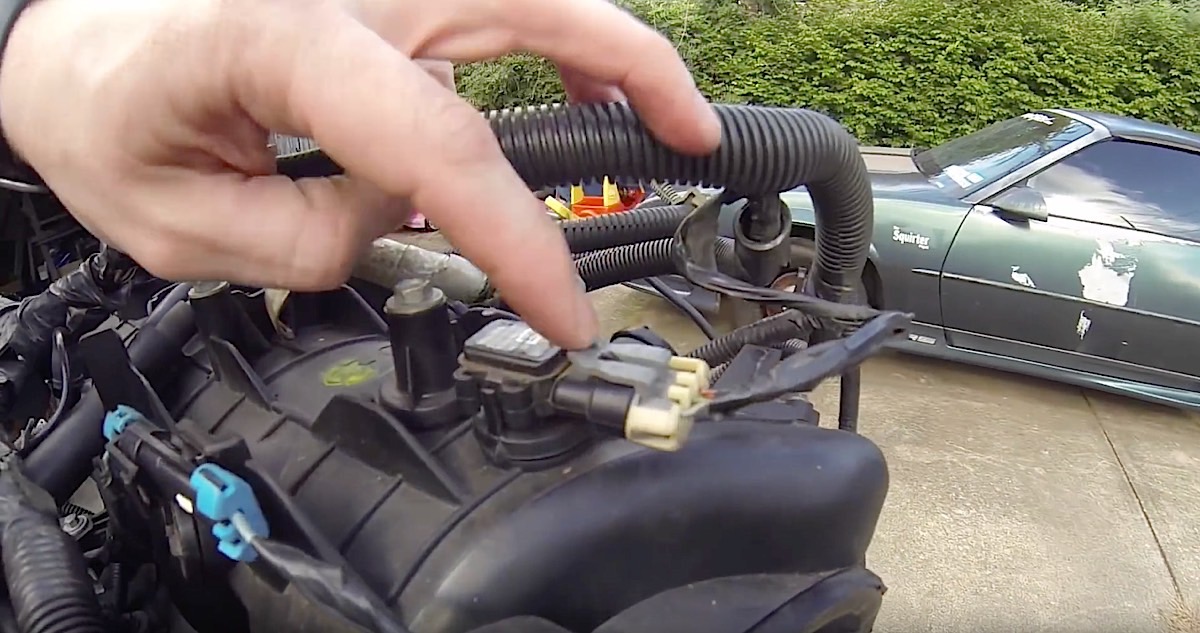
From Left to Right: The crankshaft sensor (CS) is located under the starter housing on the right side of the block, with both the throttle position sensor (TPS) and idle air control (IAC) being located at the top of the front of the intake manifold. The MAP is located at the top of the back of the manifold.
Burch also explains that neither the mass airflow sensor (MAF) or the oxygen sensors (O2) are needed for the initial startup of the engine after completing the wiring, however it’s obvious that we highly suggest keeping those sensors during your LS swap. Burch continues with the crankshaft sensor (CS), which is another critical component necessary for the initial wiring, stating that the ECU will need to measure the rotation of the crankshaft. The throttle position sensor (TPS), idle air control valve (IAC), and manifold air pressure (MAP) are three more sensors that will need to be used too.
Getting Down To The Wiring
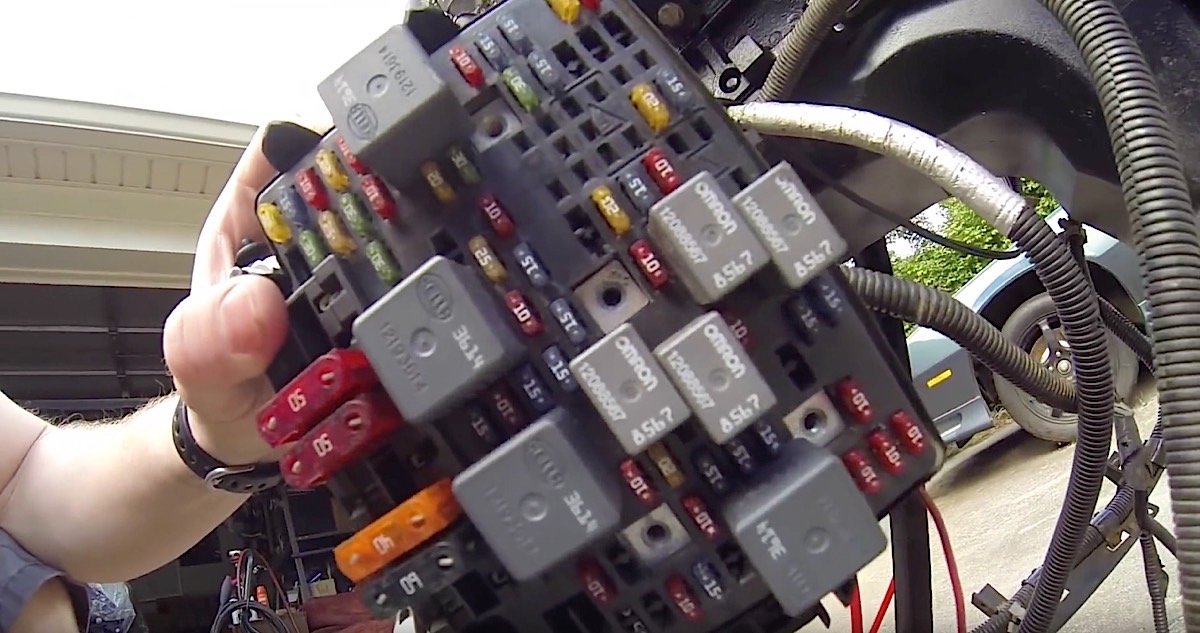
Pictured here is the front of the factory fuse panel.
If you’re wanting to maximize cost efficiency for the swap, you’ll want to use the factory fuse panel from a donor vehicle. Start by connecting power from the hot side of the battery to the panel’s main power terminal, which ensures all of the fuses in the fuse panel will receive power once you’ve connected the negative side of the battery. Next, you’ll want to find the ignition switch wire (usually a grey colored wire) and wire it to pin number A9 for the ignition switch, which is under block C1 on the fuse panel.
Once you’ve done that, you can now connect the negative side of the battery. As Burch says in the video, you should instantly hear the fuse for the repaly pump begin to prime, ensuring you have power to the ignition switch.
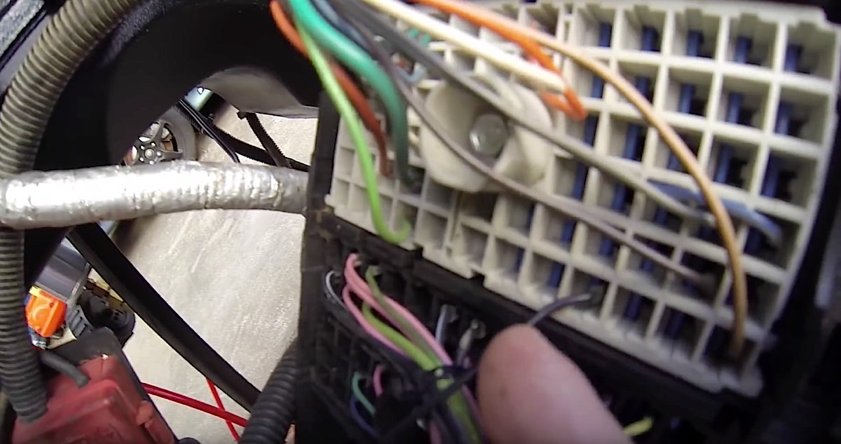
Here's a closeup of the ignition switch (grey wire) wired into the fuse for A9 under block C1.
Final Thoughts
While Burch himself explained this method to be the easiest and most efficient way of wiring your new LS swapped engine, in the end, it’s definitely ideal to ensure all of your sensors are plugged in and wired correctly to ensure everything runs safely with the new swap. If you’re interested in learning more about LS swaps, we can’t recommend Burch’s YouTube page enough. He has a lot of videos surrounding LS swaps and how-to’s.